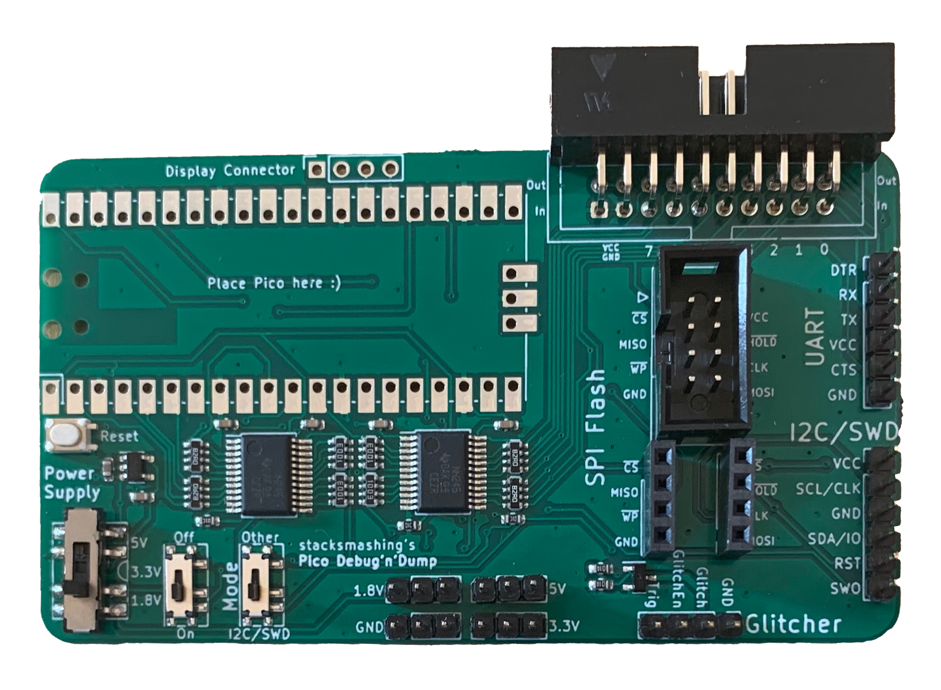
This is currently being updated, please bare with me a couple of days :)
Pico Debug’n’Dump projects:
- Example/Bringup firmware
- Transparent UART bridge with display - Ready to use binary
- flashrom serprog compatible flash programmer
- PDnD lib - library for driving the debug’n’dump
- AirTag glitcher
Quickstart
Programming it
To program the PDND simply hold down the programming button on the Pico and press reset. This will put the Pico into programming mode and it will appear as a mass storage device.
For testing I recommend downloading the UART firmware here and shortening UART TX & RX with a jumper header. Make sure the power-supply is turned on and then see if you get an echo with picocom (or your favourite UART terminal).
The 20-pin conector
The 20-pin connector has 8 inputs and 8 outputs that go directly into the level-shifters. The numbers for the pins are printed on the PCB.
The two leftover ‘upper’ pins on the Input row are GND, and on the output row are VCC.
The switches
The Pico Debug’n’Dump has three switches:
- The reset switch will reset the Pico and put everything in high-impedance mode
- The left most switches between 5V, 3.3V and 1.8V power levels
- The middle switches on or off the power-supply - if it’s turned off you can supply voltage to the level shifters from your target, i.e. if it’s running at a wonky voltage such as 2.5V or so
- The right switch (“Mode”) switches between I2C & SWD mode and all other modes - ensure this one is always in the right position for what you measure
Soldering
If you don’t have a fine soldering iron I strongly suggest that you use pin-headers on your Pico to make soldering easier - especially around the reset switch :) If you want to try without headers you can also just take one of the gold pins of the pin header and solder it on bottom and top without the plastic part.
Otherwise, just solder in the headers etc as shown in the picture below:

And then solder on the Pico :)
OLED
To enable the OLED you need to solder the two solder jumpers on the back of the Debug’n’Dump: The OLEDs come in two different versions (with VCC and GND switched), just solder the jumper to fit your OLED.
!! Also make sure to put electrical tape on the underside of the display to prevent short circuits !!
Compatible example OLEDs: